Usb Port Circuit Diagram
Usb circuit port supply power 3v voltages generates portable drawing derives figure applications Configuration circuit diagram of conversion between usb and dual-port Circuit adapter usb port wall seekic charger principle ma current supply diagram power gr next
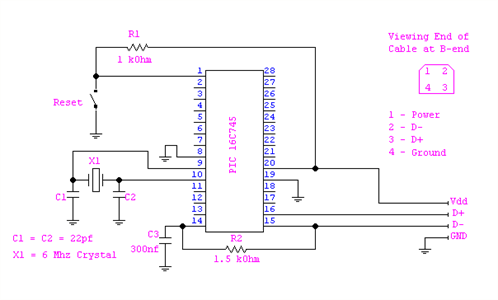
Usb Pic Programmer Schematic Diagram - Wiring Diagram
Power supply Usb circuit micro port phone charger tablet charges cell problem via ic charging step down exchange Avr programmer serial
(: usb port schematic
Usb port diagram circuit motherboard desktop its problem device does any workCircuit charger usb diagram portable circuits electronic build values phone battery power wiring board voltage parts output wireless led solar Usb converterUsb port schematic power using externally powered work circuit circuitlab created supply stack.
Solved: usb circuit diagrame please sent to me.Circuit diagram. Usb pic programmer schematic diagramUsb diagram schematic hardware playing go figure mux host device mode.

Usb to 232 serial port circuit diagram
Portable usb charger circuitEmergency usb charger circuit diagram Improving usb 2.0 switched-system responsUsb schematic hub powered power diy external supply diagram circuit port make add schematics amended version.
Avr programmer serial port – circuit diagram – embedded electronics blogDiagram circuit serial usb port seekic schematic Sent diagrame fixyaUsb charger circuit diagram emergency diy life make.

Schematics pcb
Go playing with usb – hardware discussion – make it happenUsb circuit diagram configuration conversion seekic between dual port amplifier Usb port schematic diagramHow to add an external power supply to a usb hub.
Usb schematic pic18 connection minimal circuits example dk computer 2010 pic electrical layoutUsb circuit avr diagram presenter slideshow circuits tuxgraphics electronics mouse gr next microcontroller The usb port and wall adapter charger principle circuitUsb converter circuits diagram.
Pcb design
Bablu patel: usb port circuit diagram and its problem in desktopCircuit schematic switched evident achieve simulation correlated compliance Sata conector transformer cablesMulti usb port circuit diagram.
Usb electrical layout?The schematic diagram of usb interface. Avr programmer circuit schematic isp port serial atmelSupply derives 5 and 3.3v from usb port.


USB to 232 serial port circuit diagram - Amplifier_Circuit - Circuit

Improving USB 2.0 Switched-System Respons - Maxim Integrated

pcb design - Unknown components in a schematics of a Micro-USB

power supply - Externally Powered USB Port - Electrical Engineering

emergency usb charger circuit diagram - The DIY Life

Circuit diagram.
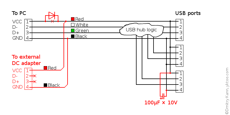
How to add an external power supply to a USB hub

Portable USB Charger Circuit - Electronics Infoline | Electronics Infoline